US Navy is Updating their Vintage CASS Testing System

March 19th, 2010

CASS Test System

CASS Test System

The Navy recently awarded an $83 million contract for e-CASS development, production and testing. The AN/USM-636(V) Consolidated Automated Support System (CASS) is the US Navy’s standard automatic test equipment family. It provides intermediate, depot and factory level support, both ashore and afloat, for testing all Navy electronics, from aircraft to ships and submarines.

CASS has been around since 1990, and it’s time for an upgrade. The Navy is planning to replace the existing 5 CASS mainframe systems with the next-generation electronic CASS (e-CASS) system. US Naval aviation currently uses 713 CASS stations for testing of aircraft electronics. CASS is also used at the Naval Sea Systems Command (NAVSEA) and in 9 foreign countries.

The new e-CASS system will replace the following 5 CASS mainframe systems:

  • Hybrid – The CASS Hybrid station provides the core test capability for general purpose electronics, computers, instruments, and flight controls.
  • Radio Frequency (RF) – The CASS RF station provides Hybrid station test capability plus electronic countermeasure, electronic counter-countermeasures, and electronic warfare support measures; and fire control, navigation, tracking, and surveillance radar, and radar altimeter support capability.
  • High Power – The CASS High Power station provides RF station capability plus the capability to test high power radar systems, such as the APG-65 and APG-73.
  • Communications/Navigation/Interrogation (CNI) – The CASS CNI station provides RF station capability plus communication, navigation, interrogation, and spread spectrum system support capability.
  • Electro-Optic (EO) – The CASS EO station provides Hybrid station test capability plus support capability for forward looking infrared, lasers/ designators, laser range finders, and visual systems.

In addition to these systems, the Navy uses a mobile CASS variety called the Reconfigurable Transportable CASS (RTCASS), supplied by Boeing. RTCASS provides a man-portable CASS configuration using COTS hardware and software to meet USMC V-22 and H-1 support requirements as well as to replace mainframe CASS stations at USMC fixed wing aircraft (EA-6B, F/A-18 and AV-8B) support sites.

Lockheed Martin, Boeing,  and Northrop Grumman supplies CASS electro-optic subsystem and DRS Technologies provides CASS high-power subsystems. (source www.defenseindustrydaily.com)

New Industry Forum Advocates Collaboration and Interoperability of Vendor Test Tools

March 17th, 2010

Network Test Automation Forum brings together commercial testing vendors, test equipment vendors, and other industry experts to create interoperable testing solutions for service providers, network equipment manufacturers, and other enterprise organizations with large network deployments.

Fremont, Calif. – March 16, 2010 – Leading companies from across the communications and networking industries including BreakingPoint Systems, BT, Cisco, Empirix, Ericsson, EXFO, Fanfare Software, Ixia, JDSU, Spirent Communications, and Verizon today announced that they have joined forces to form the Network Test Automation Forum (NTAF), www.ntaforum.org, a global effort designed to promote interoperability between test tools and to simplify lab automation efforts. With representation from service providers, network equipment manufacturers and test & measurement vendors, NTAF advocates a customer-centric, device-agnostic framework that reduces time, complexity, and cost of product test cycles.

NTAF represents a fundamental shift from the stand-alone and proprietary approaches to an open lab automation approach. The forum asks test equipment vendors to collaborate with their customers to define an open and advanced automation framework. Through the agreement and adoption of multi-vendor technical architectures for test automation systems, test engineers and lab managers will benefit from accelerated deployment of next generation network products and services.

“Our goal is to provide complete transparency in the Forum’s activities and ensure a level playing field for all members.” said Keith Kidd, president of NTAF. “By encouraging industry wide participation, NTAF is working toward establishing
interoperable testing solutions for service providers, network equipment manufacturers, and other enterprise organizations with large network deployments.”

About Network Test Automation Forum (NTAF)
The Network Test Automation Forum brings together users, vendors, and other telecommunications and data communications industry experts for the purpose of creating interoperable testing solutions for service providers, network equipment manufacturers, and other enterprise organizations with large network deployments.
NTAF is professionally managed by Association Management Solutions (AMS). For over a decade, AMS has provided leading technology groups, associations and standards bodies with a powerful combination of experience, dedicated staff, internal technology development, event services and strategic marketing resources to meet its clients, goals. Some of AMS’ clients include: Broadband Forum, IETF, Optical Internetworking Forum (OIF), MultiService Forum (MSF) and the Gaming Standards Association (GSA). (source ntaforum.org)

Mobile Radio Tags Trending Up in Korea

March 15th, 2010

Korea Sets Trend in Mobile Radio Tags

Radio frequency identification (RFID) technology was introduced during the first decade of the new millennium with much fanfare. But the radio tags were practically limited to just replacing conventional barcodes.

In this climate, experts point out that the hype originally promised by RFID would be realized only when its applications go mobile and Korea is currently leading the world in the shift toward mobility. Mobile RFID is based on portable readers imbedded in such wireless devices as cell phones with which people can check detailed data of groceries or movie previews by attaching their handsets to radio tags on vegetable wraps or movie posters.

“No matter how many radio tags are around us sporting fancy applications, its usefulness would not be realized if a number of people do not carry the readers,” a spokesperson at the Mobile RFID Forum said.

“In my view, the idea of ubiquitous RFID readers will be materialized when they are incorporated in such devices as cellular phones or other handheld devices. Korea is setting the global trend.”

Entities both from the public and private sectors convened in 2004 to form a Mobile RFID Forum involving the state-run Electronics and Telecommunications Research Institute (ETRI), Samsung Electronics, LG Electronics and SK Telecom. The companies and organizations have finished pilot tests geared toward checking the commercial viability of mobile RFID, faster than competitors in other countries. On top of commercial deployment, Asia’s fourth-largest economy has taken the initiative in technological advances as demonstrated at an international conference on RFID standards. Korea hosted the conference, which started Monday to continue through March 26 on Jeju Island, and asked for 16 technologies to be made global standards, or around 16 percent of the 68 overall proposals. Of these, observers predict that the country’s offers in mobile RFID and real-time location systems are highly likely to be endorsed because the country is ahead of the pack in these segments.

Then, Korea will be able to preempt the mobile RFID markets, which are expected to explode in the not-so-distant future, said the Ministry of Knowledge Economy. The RFID tag is a small integrated-circuit chip together with a radio circuit. The tiny tags emit radio waves so that its identification code can be scanned from a distance through a reader. The cutting-edge technology has been expected to offer a variety of information on any product like their ingredients, origins, producers and transportation histories as well. However, the hitch was that the fixed reader of the mobile RFID was not available to the general public. This prompted many countries to come up with wireless readers but they were prone to mistakes in recognizing the tags accurately. To tackle the problems, many Korean researchers have worked on improving the precision of the readers in motion to make a substantial advancement in the studies, according to the Mobile RFID Forum.

(source www.koreatimes.co.kr)

Test Equipment Connection Now Offers TECBID Auction Sales Channel

March 4th, 2010

Test Equipment Connection Corp. announced today that is has expanded its business platform by offering TECBID, an auction style sales channel allowing customers to make offers on select test and measurement equipment for sale.

“We are aggressively buying test equipment assets from companies that are downsizing, consolidating or insolvent.” said President and COO Mike Novello. “TECBID will help our customers acquire these assets at excellent prices and allow for faster turnover of large lots and distressed inventory we buy or take in under consignment agreement. We now can better manage a wider variety of electronic industry assets and our customers benefit from this efficiency.”

About Test Equipment Connection Corporation:

Test Equipment Connection Corp., Test Equipment Connection Pte. Ltd., and TE Connection Asia Limited are industry-leading suppliers of new, refurbished and second-hand electronic test and measurement (“T&M”) equipment. The companies sell, buy, lease, rent, trade, repair and calibrate over 315 manufacturers including Anritsu, Rohde & Schwarz, Agilent, Tektronix, Advantest, LeCroy, Chroma and Fluke, with thousands of products available. The companies are a single source supplier with in-house calibration laboratories assuring that customers receive only the highest quality T&M equipment and support. Test Equipment Connection Corporation has over 250,000 customers, a 45,000 square foot warehouse and repair facility in the US, and 17 years of profitability and financial strength.

Visit www.testequipmentconnection.com or email sales@testequipmentconnection.com for more information.

Download this Press Release – Auction.pdf

Test Equipment Connection Corporation

30 Skyline Drive
Lake Mary, FL 32746 USA   (800) 615-8378 x 141

Press Release Contact Information:

Test Equipment Connection Pte. Ltd.
6 Battery Road
#31-00 Standard Chartered Bank Building
Singapore 049909

Telephone: 65-6320-8596

TE Connection Asia, Ltd.
Unit 13, 16 / FL Fotan Industrial Centre
26-28 Au Pui Wan Street
Fotan Shatin N.T.    Hong Kong: 852-2690-1360 China: 86 136-3217-2095

Fluke Awarded Federal Grant to Establish Smart Grid Calibration Standard

March 1st, 2010

Fluke awarded $1.4 million federal grant to establish Smart Grid calibration standard

The goal is to increase electrical reliability and reduce power interruptions

EVERETT, Wash. – Fluke Corporation, the global leader in handheld electronic test and measurement technology and electrical calibration, will receive $1.4 million in federal stimulus funding, made possible by the American Recovery and Reinvestment Act, to ensure the Smart Grid is reliable and stable, and ready to accept power from renewable resources including wind and solar.

Fluke Corporation, a division of Danaher Corporation (NYSE: DHR), was chosen to create a new calibration technology that is a catalyst for creating a standard with which electricity flowing into the Smart Grid will be evaluated. The standard will enable consistent measurement of electricity from all sources, including renewable resources such as wind and solar. The grant was awarded by the U.S. Commerce Department’s National Institute of Standards and Technology (NIST) in the area of Measurement Science and Engineering Research to support research in areas deemed of critical national importance. “This grant is a testament to the innovations we’ve brought to the field of electrical measurement,” said Barbara Hulit, Fluke president.

“We are excited at the prospect of helping develop a measurement standard that makes the entire U.S. Smart Grid more stable, while utilizing renewable energy efficiently and effectively.”

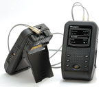
Looming Issue: Why the Smart Grid needs an electrical measurement standard Fluke’s new calibration technology will be used to calibrate Phasor Measurement Units (PMUs), a gating technology that measures the health of the electrical power grid. PMUs play a vital role in the deployment of the Smart Grid, by measuring and evaluating power flowing into the grid from increasingly diverse sources. Grid distribution centers use this critical information to determine where and when to send power across transmission lines, leading to more efficient use of energy and lessening the risk of power interruptions and outages. PMUs identify the preconditions that lead to power interruptions.

The U.S.-Canada investigation into the Northeast blackout of 2003, which disrupted power to an estimated 45 million people in eight U.S. states and 10 million people in Ontario, hypothesized that had a system of PMUs been in place, the grid collapse could have been avoided. According to a recent study at Lawrence Berkeley National Laboratory, power interruptions cost the U.S. economy about $79 billion annually, or about one third of what the nation spends on electricity. Add to this the need for the Smart Grid to carry energy from renewable sources, and there is an even higher potential for future conflicts to occur, putting the U.S. Smart Grid at risk for power interruptions.

“Modernizing the electric grid and improving power system reliability requires very precise electrical measurements. PMUs provide those. They also allow the grid to utilize energy from renewable resources and increase transmission throughput. At present, the testing and verification method for PMUs is unclear. That’s why the Smart Grid needs one measurement standard,” said Warren Wong, director of engineering for Fluke Calibration.

“With a PMU calibrator, we’ll have a standard that can be used to uniformly evaluate the proper operation of these devices. That could really minimize the risk of power conditions that lead to blackouts.”

NIST received over 1,300 proposals for the grants and Fluke was one of only 27 companies awarded grants in the area of  measurement science and engineering research. Fluke will develop the calibrator over the next 26 months, and as part of the grant, will invest $390,000 of its own money in the development effort.

About Fluke
Fluke Corporation is the leader in compact, professional electronic test tools. Fluke customers are technicians, engineers, electricians, metrologists and building diagnostic professionals who install, troubleshoot, and manage industrial electrical and electronic equipment and calibration processes for quality control as well as conducting building restoration and remediation services. In just the past year Fluke tools won more than 15 industry awards including Test and Measurement World Best in Test, Control Engineering Engineer’s Choice, and Plant Engineering Product of the Year. Fluke is a registered trademark of Fluke Corporation in the United States and/or other countries. The names of actual companies and products mentioned herein may be the trademarks of their respective owners.

About Danaher
Danaher is a diversified technology leader that designs, manufactures, and markets innovative products and services to professional, medical, industrial, and commercial customers. Our portfolio of premier brands is among the most highly recognized in each of the markets we serve. Driven by a foundation provided by the Danaher Business System, our 47,000 associates serve customers in more than 125 countries and generated $11.2 billion of revenue in 2009. For more information please visit our Web site: www.danaher.com.  (source us.fluke.com)

What is a Phasor measurement unit ?
A Phasor measurement unit (PMU) measures the electrical waves on an electricity grid to determine the health of the system. In power engineering, these are also commonly referred to as synchrophasors and are considered one of the most important measuring devices in the future of power systems (smart grid). A PMU can be a dedicated device, or the PMU function can be incorporated into a protective relay or other device.

What is a Phasor network ?
A phasor network consists of phasor measurement units (PMUs) dispersed throughout the electricity system, Phasor Data Concentrators (PDC) to collect the information and a Supervisory Control And Data Acquisition (SCADA) system at the central control facility. Such a network is used in Wide Area Measurement Systems (WAMS), the first of which was begun in 2000 by the Bonneville Power Administration. The complete network requires rapid data transfer within the frequency of sampling of the phasor data. GPS time stamping can provide a theoretical accuracy of synchronization better than 1 microsecond. “Clocks need to be accurate to plus or minus 500 nanoseconds to provide the one microsecond time standard needed by each device performing synchrophasor measurement.”  For 60Hz systems, PMUs must deliver between 10 and 30 synchronous reports per second depending on the application. The PDC correlates the data, and controls and monitors the PMUs (from a dozen up to 60). At the central control facility, the SCADA system presents system wide data on all generators and substations in the system every 2 to 10 seconds. PMUs often use phone lines to connect to PDC, which then send data to the SCADA and/or Wide Area Measurement System (WAMS) server. PMUs from multiple vendors can yield inaccurate readings. In one test, readings differed by 47 microseconds- or a difference of 1 degree of at 60Hz- an unacceptable variance. China’s solution to the problem was to build all its own PMUs adhering to its own specifications and standards so there would be no multi-vendor source of conflicts, standards, protocols, or performance characteristics.

The Main Interconnections of the U.S. Electric Power Grid

The 10 North American Electric Reliability Council Regions:
ECAR – East Central Area Reliability Coordination Agreement
ERCOT – Electric Reliability Council of Texas
FRCC – Florida Reliability Coordinating Council
MAAC – Mid-Atlantic Area Council
MAIN – Mid-America Interconnected Network
MAPP – Mid-Continent Area Power Pool
NPCC – Northeast Power Coordinating Council
SERC – Southeastern Electric Reliability Council
SPP – Southwest Power Pool
WSCC – Western Systems Coordinating Council
Note: The Alaska Systems Coordinating Council (ASCC) is an affiliate NERC member.  (Source: North American Electric Reliability Council)

WiMAX Testing with the Anritsu BTS Master

February 25th, 2010

BTS Master by Anritsu

BTS Master by Anritsu

Handheld integrated multi-function test tool RF engineers and technicians in the field need a lightweight, practical, and rugged test solution that can perform all the measurements needed for installation and maintenance of modern cell sites. That solution is the BTS Master MT8222A. It combines the functionality of Anritsu’s high performance-handheld products, including the MS2721B Spectrum Master and the MS2024A and MS2026A Cable and Antenna Analyzer. This combined product weighs less than 4 kg. (9lbs.). The MT8222A provides users with cable and antenna analysis, spectrum analysis, power meter, W-CDMA/HSDPA, GSM/GPRS/EDGE, CDMA/EVDO, Fixed WiMAX, Mobile WiMAX and TD-SCDMA, RF and Demod measurements and W-CDMA/HSDPA CDMA/EVDO, Mobile WiMAX and TD-SCDMA Over the Air (OTA), channel scanner, Interference Analyzer, variable Bias Tee, Bit Error Rate Tester (BERT) and Power Monitor. So technicians can eliminate the need to carry several independent instruments and instead get the job done with the MT8222A – an optimal combination of Anritsu’s high performinghandheld instruments.

BTS Master MT8222A/10A/19/25/27/31/51 On Special Now and Loaded with Options

Easy to use
Coming from the leader in cable and antenna analysis, it’s no surprise that the BTS Master MT8222A is very easy to operate and requires little or no training. Users will enjoy the bright 8.5 in. (215 mm.) color TFT display – easy to read even in broad daylight. Up to six markers can be displayed on the screen including noise markers and frequency counter markers in the Spectrum Analyzer mode.

Keep on going – wherever you like The BTS Master runs for more than 2.5 hours on a single, rechargeable Li-ion battery. So users have the time and freedom to move from ground installations to the highest towers, or anywhere where critical measurements are needed. Plus, when it’s time to replace the battery, it takes no time at all, and requires no tools.
Eight Built-in Languages While fluent in English, Spanish, German, French, Japanese, Chinese, Italian and Korean, the MT8222A user can also customize two additional languages using Master Software Tools.

Fiber Optic and Copper Certification is a Snap

February 23rd, 2010

with the Megger Structured Cable Testers and Fiber Optic Adapters

SCT Series
Structured Cable Tester
Certifies Category 7, 6a, 6 and 5e cabling
Exceeds Level IV Accuracy
1 to 1000 MHz frequency range

Most intuitive and easy to operate LAN certification tester on the market

Powerful diagnostics pinpoint the distance to link disturbances on each measured pair

Best return on your investment given low operating costs and superior reliability

The SCT Series is a high-performance tester for certifying and evaluating copper and fiber cabling installations.

The SCT Series are unmatched for flexibility with improved device features including 1/4 VGA color display, USB & serial ports; compact flash, secure digital, multimedia card storage, unit-to-unit audio and 64 Mb of internal memory.

Designed for cable installers and network owners who need to certify the performance of high-speed cabling to today’s industry standards and tomorrow’s emerging standards, the SCT Series delivers unmatched performance and accuracy.

Whether certifying cabling installations, troubleshooting problems, migrating to a high-speed network, or re-certifying after add-ins, moves or expansions, the SCT Series exceeds expectations.

Certify singlemode and multimode fiber optic links at 850, 1300, 1310 and 1550 nm wavelengths

Provide fully compliant Tier 1 Certification

Capabilities include length, loss and power measurements, power meter and light source

Perform bi-directional testing without swapping primary and secondary units

Integrated VFL for diagnosing link problems

Most intuitive and easy to operate fiber optic certification tester on the market

SCT-MMA  Fiber Optic Adapters
As the number of fiber optic links in the network increases it’s essential that your certification tester seamlessly certifies both copper and fiber, efficiently combining all media results together for analysis and reporting. The SCT-MMA and SCT-SMA fiber optic adapters fulfill this need by converting the SCT into a fully compliant Tier 1 multimode and singlemode fiber optic certification tester. Now you can confidently certify all of your copper and fiber optic links with the snap of an adapter.

The SCT fiber optic solution offers powerful capability and features including length measurement, two-fiber, dual-wavelength loss measurements, single and bi-directional fiber measurements, power meter mode, light source mode, Fiber-Map and visual fault locator (VFL) capability. The SCT Autotest differs from other units by returning a length measurement and four loss measurements when testing dual fibers.

Fully Compliant Tier 1 Certification

The SCT fiber optic adapters create a fully Tier 1 compliant testing solution measuring length, loss, and polarity.

The SCT also differs from some units by performing bi-directional testing on two fibers at two wavelengths without exchanging the Primary and Secondary units.

Testing Fiber and Copper is a Snap
Fiber optic and copper certification is a snap with the SCT. Switching between copper and fiber certification is faster and more reliable than any other solution, simply snap in an adapter. Only the SCT allows the user to create dual media projects that store all necessary copper and fiber optic certification parameters in one project. With dual media projects and the ability to automatically recognize copper and fiber optic adapters the SCT can seamlessly switch between copper and fiber optic testing and project parameters with the snap of an adapter.

Visual Fault Locator
The SCT fiber optic adapters include a visual fault locator (VFL) as an easy to use troubleshooting tool. The VFL can locate and visibly identify faults on fiber optic cables. The VFL features a 635-nm visible red laser source. The presence of the VFL’s red light indicates a trouble spot in the fiber such as a break or sharp bend. The VFL can be used with either multimode or singlemode fiber. The VFL creates a continuous or modulated light source powerful enough to escape from sharp bends and breaks in jacketed or bare fiber as well as poorly mated connectors, making it ideal for locating trouble spots in jumper cables, distribution frames, splice strays, patch panels, cable splice points and for tracing fiber

United Launch Alliance Launches Solar Observatory

February 16th, 2010

United Launch Alliance Launches Solar Observatory Mission for NASA

A United Launch Alliance Atlas V with NASA’s Solar Dynamics Observatory launches from its Space Launch Complex-41launch pad at 10:23 a.m. EST here today. SDO is the first satellite of NASA’s Living with a Star (LWS) program. Its purpose isto examine the sun, the source of all space weather. Photo by Pat Corkery, United Launch Alliance.

Cape Canaveral, Fla., (Feb. 11, 2010) – United Launch Alliance successfully launched NASA’s latest scientific exploration mission, the Solar Dynamics Observatory (SDO), aboard an Atlas V rocket from Space Launch Complex-41 at 10:23 a.m.EST today. This was ULA’s first launch of 2010 and marked the 100th use of the commercial Atlas Centaur launch vehiclesince its first launch on July 29, 1990. The first commercial launch was NASA’s Combined Release and Radiation Effects Satellite (CRRES) spacecraft.

“ULA is extremely proud to be a part of the SDO mission, NASA’s first satellite launch of its ‘Living with a Star’ program,” saidMark Wilkins, ULA Vice President, Atlas Product Line. “This launch culminates years of hard work by our NASA customer andour ULA launch team. It’s appropriate that our 100th use of a commercial Atlas Centaur was for a NASA mission since Centaur was originally developed for NASA’s lunar program.”

The Centaur upper stage began launching as a NASA vehicle on top of Atlas in 1962 to land surveyor spacecraft on the Moon in preparation for manned landings by Apollo. As the original government-managed Atlas Centaur program was nearing its end, it was resurrected as a commercial vehicle in the late 1980s by General Dynamics. Upgraded versions of

Atlas Centaur have been flying missions since 1990, with the SDO launch marking its 100th flight. Centaur is probably most famous for its role in NASA’s recent Lunar Reconnaissance Orbiter and Lunar Crater Observation and Sensing Satellite (LRO/LCROSS) mission where it crashed into the Moon in October 2009 to help NASA confirm the presence of water at the Moon’s South Pole.

“Our Atlas launches of the past two decades would not be the success they were without the Centaur upper stage conducting its mission flawlessly,” Wilkins said. “We look forward to the next 100 Centaur missions.”

The SDO mission was launched aboard an Atlas V 401 configuration and it used a single common core booster poweredby the RD-180 engine.

ULA’s next launch is the NASA/NOAA Geostationary Operational Environmental Satellite P (GOES P) mission, which will belaunched aboard a Delta IV rocket on behalf of Boeing Launch Services. The launch is scheduled for Mar. 1, 6:19 p.m. EST,from Space Launch Complex-37 here. (source ulalaunch.com)


Clearing the 700 MHz Frequency Band

February 12th, 2010

FCC ADOPTS ORDER TO CLEAR THE 700 MHz FREQUENCY FOR PUBLIC SAFETY AND NEXT GENERATION CONSUMER USERS


Washington, D.C. – Jan. 15th 2010 -  the Federal Communications Commission adopted an Order and Further Notice of Proposed Rulemaking prohibiting the further distribution and sale of devices that operate in the 700 MHz frequency.  This action helps complete an important component of the DTV Transition by clearing the 700 MHz band to enable the rollout of communications services for public safety and the deployment of next generation 4G wireless devices for consumers.

The order will primarily impact the use of wireless microphone systems that currently operate in the 700 MHz band.  These unlicensed devices cannot continue to operate in this band because they may cause harmful interference to public safety entities and next generation consumers devices that will be utilizing the 700 MHz frequency.  Thus, the Commission is making clear that no devices utilizing this frequency may be sold or distributed.  In order to ensure that individuals and groups currently using unauthorized devices in this band have ample time to transition to appropriate frequencies, the FCC is providing a sunset period until June 12, 2010, one year from the DTV Transition.

The Commission is also unveiling an aggressive consumer outreach plan in order to assist consumers who have previously purchased wireless microphone systems and other related devices that utilized the 700 MHz  band. Through the Commission’s website, www.fcc.gov/cgb/wirelessmicrophones, consumers can learn whether their wireless device is currently operating in the prohibited band and whether their devices may be retuned to operate on another band.  Consumers may also call 1-888-CALL-FCC to ask questions regarding this transition.

LeCroy WaveAce – Using the Help Function Demo

February 11th, 2010

The WaveAce combines long memory, a color display, extensive  measurement capabilities, advanced triggering and excellent connectivity to improve troubleshooting and shorten debug time with bandwidths from 40 MHz to 300 MHz. The built-in context sensitive Help explains the functions of each knob, button and menu and is available in a 8 languages.


The LeCroy WaveAce 204 – Debug with Confidence – 40 MHz – 300 MHz
WaveAce 204 Tools for Improved Debugging:

  • Long Capture – 10 kpts/Ch and 20 kpts
  • interleaved to capture more time and show more waveform details
  • Math and Measure – 4 basic math functions plus FFT and 32 automatic measurement parameters
  • Connectivity – USB for mass storage, printing and PC control plus LAN for fast data transfer
  • Pass/Fail Testing – quickly identify failing devices and when failures occur
  • Large Internal Storage – save 20 waveforms and 20 setups to the internal WaveAce memory
  • Waveform Sequence Recorder – record and play back up to 2,500 waveforms