Conductive Airframes and Testing

May 3rd, 2011

Testing Composite Materials

Composite materials, which are essentially high strength engineering plastics, are being used more and more widely, especially in the construction of aircraft bodies.

One of the world’s largest manufacturers of commercial jetliners and military aircraft combined has, for example, announced that as much as 50 percent of the primary structure – including the fuselage and wing – on a new passenger aircraft will be made of composite materials.
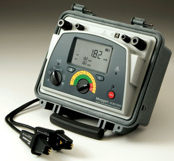
MEGGER DLRO10
Megger DLRO10 Digital Low Resistance Ohmmeter – The MEGGER DUCTER DLRO-10 and DUCTER DLRO-10X bring new standards to low resistance measurement.

Clearly there is a need for effective testing techniques for assemblies made from these novel materials. Since composite materials are inherently non-conductive, however, it is initially difficult to see what role electrical test methods can play in meeting this requirement.

The key to the answer is that electrically conductivity is, for many reasons, an essential requirement in airframes. For example, conductive airframes play an important role in dissipating the energy from lightning strikes and in preventing the build up of static charges. They also provide essential electromagnetic shielding, and allow the correct operation of many types of circuit protective device.

MEGGER DLRO200-EN

Megger DLRO200-EN 200 AMP Digital Low Resistance Ohmmeter The new Megger DLRO200EN and DLRO200-115V are designed to measure contact resistance in high voltage circuit breakers, disconnecting switches

For these reasons, the composites used in airframe construction, at least for civil aircraft, invariably include a thin metal mesh specifically to provide electrical conductivity.

During the construction of the airframe, great care is taken to ensure that the meshes in individual components are electrically bonded together, since faulty bonding would not only compromise the effectiveness of the shielding provided by the mesh, but could also lead to sparking, especially during electrical storms. Such sparking, especially if it occurred in the proximity of the aircraft’s fuel systems, could have serious consequences.

Megger DLRO10HD
Low Resistance Ohmmeter – Megger Model# 1000-348 Catalog# DLRO10HDDual power 10 A low resistance ohmmeter High or low output power selection for condition diagnosis Rechargeable battery or line power supply

It’s easy to see that a reliable method of testing the bonding and the overall integrity of the mesh is essential. For this purpose, low resistance testing, which is easy to carry out with moderately priced test equipment, has much to recommend it.

The principle of low resistance testing is straightforward – a known current is injected into the item under test, and the voltage that results from this current flow is measured. Knowing the voltage and the current, the test set can easily calculate the resistance of the test object using Ohm’s law.

In practice, for dependable low resistance testing, a few refinements are necessary. Most importantly, the resistance of the test leads and the test connections will often be comparable to, and even sometimes greater than the resistance of the item under test, so accurate results will be impossible to obtain unless due allowance is made.

The best solution is to use a test set that supports four-terminal testing. With this arrangement, the current is applied through two test leads, and two entirely separate leads are used for the voltage measurement. This means that, provided the instrument measures both the current and voltage, the resistance of the test leads and connections has a negligible effect on results.

The next issues that must be carefully considered are test current and power. Low currents of up to 10 A from a source that is power limited to around 0.25 W are good for revealing contaminated connections in electrical equipment. Similar currents from power source capable of supplying, say, 25 W are better for detecting weaknesses in bonding, but some types of test objects can be damaged by the higher power available.

High current tests, which typically cover the range 10 A to 600 A, are most appropriate for measuring the current-carrying capacity of electrical equipment such as busbars and circuit breakers.

Megger’s experience with its popular DLRO family of digital low-resistance ohmmeters has shown that test currents between 2 A and 10 A are the most suitable for evaluating the capability of the conductive mesh associated with composite materials to control static build up. Testing at these currents can also reveal the type of damage to the mesh that may result from material fatigue, especially if historical reference data or data from a similar airframe know to be in good condition is available for comparison.

However, one major aircraft manufacturer determined that testing at 30 A is needed to test a large airframe’s lightning protection to provide stable, repeatable measurements in noisy hanger environments. Note that only a minority of currently available test sets, including some models in the DLRO family, are capable of working continuously with such high test currents, in combination with such high test lead resistance. Remember the instrument has to maintain the required test current through the resistance of the long test leads used as well as the resistance of the airframe being measured.

Therefore for this application we need to keep the current loop resistance to a minimum. The current leads need to be of substantial cross section and to be available with a range of test clips to suit different connection requirements. They will also need to be available in lengths from short to, for large structures, very long.

Though they have been used in small-scale applications for many years, the adoption of composite materials for large structures such as passenger jet airframes is a recent development. For this reason, the challenges of testing such structures are only now being fully addressed but, as we have seen, for airframes at least, low-resistance testing is a convenient, cost-effective and versatile option.

Megger Leads the Way in Turbine Testing

May 2nd, 2011

Believed to be the first commercially available products of their type that have been specifically designed for wind turbine applications, Megger’s new test leads eliminate the need for engineers and technicians involved in wind turbine testing to fabricate their own test leads.

Megger’s new KC series of test leads, which were developed in conjunction with leading manufacturers of wind turbines, provide a complete and convenient solution to the problem of finding reliable test leads that are long enough to be used for testing the continuity of lightning protection conductors in wind turbine blades.

Megger 1000-809
DH2 leads with duplex hand spikes and hook end Specially designed for measuring resistance of lightning protection circuit between wind turbine blade tip to ground.

Believed to be the first commercially available products of their type that have been specifically designed for wind turbine applications, Megger’s new test leads eliminate the need for engineers and technicians involved in wind turbine testing to fabricate their own test leads – a time consuming and inconvenient process – or to resort to makeshift arrangements that may deliver uncertain results.

KC-series wind turbine test leads are available 100 m, 50 m and 30 m versions, and are equally suitable for use on site or in the manufacturing plant. For convenience and ease of handling, they are supplied as standard on a heavy-duty cable reel that is fitted with a friction brake to avoid tangles when paying out the cable.

The leads are terminated with large robust Kelvin clips that have been specially designed to offer ease of use while providing the consistently reliable connections needed to ensure accurate and repeatable test results. Included with each lead set is a 5 m cable fitted with a duplex handspike for probing the lightning receptors on the tips of the turbine blades.

KC-series leads are ideally suited for use with Megger DLRO10HD low-resistance digital ohmmeters, which combine robust construction with a high test current capability. They also have an IP65 protection rating with the lid closed, and an IP54 rating when the lid is open and tests are being performed, which means that they can be safely used outdoors even when it is raining.

Megger DLRO10HD
Low Resistance Ohmmeter – Megger Model# 1000-348 Catalog# DLRO10HDDual power 10 A low resistance ohmmeter High or low output power selection for condition diagnosis

While these features make DLRO10HD ohmmeters an excellent choice for wind turbine applications, KC-series leads can also be used successfully with most modern types of low-resistance ohmmeter.

Insulation Testing Considered

April 29th, 2011

Insulation Resistance Testing

The measurement of insulation resistance provides a reliable and convenient means of monitoring the condition and state of readiness of high-capital electrical equipment. All common electrical circuitry…whether wiring, cabling, control devices, motors, transformers, generators and the like…is surrounded by some type of insulating material.

At time of manufacture, this material typically has enormous resistance, typically too high to even measure except with the highest quality testers. But when put into service, insulation begins to degrade from a variety of factors, and the decline in resistance values provides a reliable indication of the extent of this degradation, and by extension, of the expected life of the equipment.

Megger MIT520-2
Megger Model# 1000-376 Catalog # MIT520/2 – 5 and 10-kV Insulation Resistance Testers Line supply or battery operated Digital/analog backlit display

Measuring the decline and rate of change of insulation values forms the basis for “preventive/predictive maintenance”, by which the equipment is periodically monitored. Items with sufficiently high resistance are not likely to fail in the near future, and so repeat testing can be delayed appropriately to save man-hours. Conversely, items exhibiting lower resistances can be trended by their rate of decline to indicate an optimum time to take out of service for restorative maintenance, in order that they not fail in service.

Failures can also occur catastrophically, as by flooding, lightning, and extreme voltage surges. These cannot be anticipated, but insulation testing is the first step in troubleshooting and repair, and can be used to monitor the restoration of failed equipment through drying and cleaning processes.

Megger MIT510-2
Megger Model# 1000-372 Catalog # MIT510/2 – 5 and 10-kV Insulation Resistance Testers Line supply or battery operated Digital/analog backlit display

Insulation testers require a special knowledge, of greater depth than most common electrical testers. Because they are applied to insulation, a non-conductor, readings are not as self-evident as with common measurements of circuitry and components. Rather, the test item charges during the course of an insulation measurement, causing readings to change constantly over the time of the test. If this is not fully understood, the test can be rendered completely ineffective. In addition, while insulation testers themselves, despite their high voltage outputs, are not inherently dangerous, a highly charged test item can be lethal. Therefore, the operation of the tester and the nature of the charging currents must be fully understood in order for insulation testing to be both effective and safe.

Standard test methods have been widely adopted in order to expedite test time, effectively deal with the changing readings over time, and specifically identify different problems. An understanding of these methods is indispensable to effective use of an insulation tester.

Megger BM15
INSULATION RESISTANCE TESTER The BM15 and MJ15 are compact 5-kV insulation testers that are simple to use

Insulation responses to both testing and operational demands are influenced by extraneous factors such as temperature and humidity. Without proper understanding, these factors can cause misinterpretation of otherwise coherent results. Standing alone, an insulation reading of “x” Megohms can be meaningless or even misleading. When backed by proper knowledge, it is one of the most effective tools of electrical maintenance.

Is Your Resistance Low?

April 25th, 2011

Is Your Resistance Low or Are You Getting Hot?

Low resistance measurement is a well-established technique that can be used almost anywhere electrical conductivity is important – its applications range from checking the quality of earth bonds to verifying the density of graphite electrodes in aluminum refineries. Recently, however, thermal imaging has been proposed as a simple and effective solution in many of the same applications. But is it?

The real answer is that both low resistance testing and thermal imaging have their place so, in order to decide which to use where, let’s take a look at the strengths and weaknesses of each.

A big benefit of low resistance testing is that it can detect problems even when there is no current (other than the test current) flowing in the object under test. This makes it very suitable for applications such as checking weld quality, verifying the performance of lightning protection bonds, confirming the integrity of aircraft structures and testing earth systems.

Low-resistance testing is also invaluable in manufacturing applications, particularly where it is necessary to test subassemblies rather than complete systems, and for checking new or modified electrical installations prior to energisation. Thermal imaging is unlikely to be suitable for any of these applications.

A further benefit of low-resistance testing is that it provides straightforward numerical results, which can easily be recorded and, even more useful, trended as part of a predictive maintenance programme.

Having said that, low-resistance testing does, of course, have its limitations. It can’t, for example, be used on live equipment. For equipment that’s in service, therefore, it’s necessary to arrange for the supply to be isolated before carrying out the test, which is not always convenient. In addition, if there are many connections to test, low-resistance testing can be time consuming.

Turning now to thermal imaging, it’s a good way of checking for overloads and unbalanced loads, which can’t be done with a low-resistance tester. Thermal imagers also have non-electrical applications, such as finding the locations of heat loss from buildings, and detecting mechanical faults such as worn bearings in a motor, which heat up because of excessive friction.

Thermal imaging also has the reputation of being easy to use, but that’s not always the case – the operator needs to understand what they are seeing and to be able to interpret the results. For example, is a transformer overheating, or is it at its normal operating temperature? What is the load on the equipment while the test is being carried out? At what point does the temperature rise become a problem?

In high-voltage environments, such as an electrical substation, a further complication is that is often not safe to get close enough to the equipment to image it clearly. In addition, items such as fuses and circuit breakers are usually mounted in metal enclosures, and thermal imaging will not work through metal.

It is often unsafe to remove covers or open doors with the supply switched on but, by the time the supply is isolated and the covers removed, the equipment will have cooled significantly, making the thermal imaging data of dubious value.

It can also be difficult to accurately relate the thermal image to the equipment being evaluated, and it is sometimes necessary to take a normal digital photograph and then use a PC to overlay this with the thermal data. Finally, trending thermal images to identify changes over time is not particularly straightforward.

Thermal imaging is, as we have seen, a very useful technique but it complements rather than replaces low-resistance testing. And there are many applications where nothing but a low-resistance test will do. It does, however, pay to take a little care in selecting a low-resistance test set if it is to offer maximum versatility and convenience.

For example, it is all too easy to make an accidental connection to a live supply when attempting to carry out low-resistance tests, particularly when testing busbar bonds and battery straps in UPS installations. It is important, therefore, that the instrument is suitably protected.

In many test sets, this protection is provided by a fuse, but this is not particularly convenient as, if a suitable replacement is not to hand, the instrument is not useable until a replacement can be obtained. Better low-resistance testers, such as those in the Megger DLRO10 family, are intrinsically protected against connection to live supplies. With these instruments, it’s possible to carry on testing normally as soon as the errant supply has been properly isolated.

It is also important to select an instrument that can supply a test current appropriate to the application – ideally, it should offer a choice of test currents covering a wide range. This is because high test currents can, in some cases, cause unwanted heating of the test piece, while in other cases the heating caused by high currents is actually desirable, as it can help to reveal weaknesses such as broken strands in a multi-core cable.

Similarly, the usefulness of low test currents is also dependent on the application. Low currents may be a problem in some circumstances, as they make not break through the contamination in bonds. In other circumstances, however, this may be a benefit, because the same situation can provide a useful indication that contamination is present!

In addition, a low test current combined with test current reversal may eliminate the need for temperature compensation of the results, and it also has the benefit of extending battery life in portable instruments.

Finally, ease of use is a crucial factor. For maximum convenience in day-to-day use, the test set should have an intuitive user interface, and it should perform tests quickly and efficiently, otherwise it will rapidly become a constant source of irritation rather than a useful tool.

In conclusion, it’s clear that both thermal imaging and low-resistance testing are invaluable techniques and the ideal situation is to have access to test equipment for both. Only then can you be absolutely certain of providing a definitive answer to the question that we’ve all, at one time or another, asked – is your resistance low, or are you getting hot?

New Megger DLRO10HD

Megger DLRO10HD Low Resistance Ohmmeter – Megger Model# 1000-348 Catalog# DLRO10HD

Dual power 10 A low resistance ohmmeter

  • High or low output power selection for condition diagnosis
  • Rechargeable battery or line power supply, continuous operation, even with dead battery
  • 10 A for 60 seconds, less time waiting to cool, great for charging inductance
  • High input protection to 600 V, inadvertent connection to line or UPS voltage will not blow a fuse
  • Heavy duty case: IP 65 lid closed, IP54 operational (battery operation only)
  • Rotary switch selects one of five test modes, including auto start on connection, giving ease of use

Equally at home in the laboratory, the workshop or in the field, on the bench or on the ground, the new heavy duty Megger DLRO10HD low resistance ohmmeter combines rugged construction with accuracy and ease of use. It features an internal rechargeable battery and can also operate from a mains supply, even if the battery is completely flat.

IP Rating – What Does It Mean?

April 22nd, 2011

Somewhere in the fine print of most product bulletins, you’ll find an IP rating. Is this just “boilerplate”? No! It gives vital information that could be critical to your application.

Megger products are typically rated to IP54. (If you want to sound thoroughly knowledgeable, that’s IP five-four, not fifty-four. Each digit relates to a separate rating, not to each other.) “IP” stands for “ingress protection”, the degree to which the instrument can withstand invasion by foreign matter. This has been established by the IEC (International Electrotechnical Commission), in their Standard 529. The higher the number, the better the protection. The first digit refers to particulate ingress. This reflects the degree to which solid objects can penetrate the enclosure. The typical Megger rating of 5 indicates “dust protected”, as well as protected from access with a wire down to 1.0 mm. There is only one higher category: “dust tight”.

The second digit refers to moisture ingress. A rating of 4 indicates “splashing water, any direction”. The higher ratings of 6 through 8 indicate “powerful jetting water” and “temporary” or “continuous” immersion. Not too many electricians need to work under water!

So what? Well, suppose an instrument under consideration was rated only to IP43. What would that tell you about its usability? Could it be thoroughly utilized in a quarry or cement plant? Hardly! The particulate rating 4 indicates “objects equal or greater than 1 mm”. That’s a boulder in comparison to particles typically produced by industrial processes. Flying dust could put the unit out of commission before the purchasing agent is done stalling payment. What about a paper mill? Wrong application again! The moisture rating 3 covers “spraying water, up to 60° angle from vertical.” This is adequate protection for occasional incidental encounters, but still leaves a wide margin for invasion where water is a common hazard. Moisture could penetrate the unit, corrode and short out the board, and produce nagging repair delays that could critically disrupt a time-focused preventive maintenance program.

By contrast, a typical Megger model rated to IP 54 will perform up to and beyond expectations in all of these environments. Protected against dust and moisture under all but the harshest of conditions, the instrument will meet the test for a full life expectancy. Avoid the embarrassment of having to tell the “boss” or purchasing agent that a unit has failed when they still think of it as “brand new”. Make a mental review of the types of environment in which the instrument will possibly be used, the nature of foreign materials to be encountered, and what that will demand in terms of IP rating. Then purchase a unit that matches or exceeds that requirement, and don’t be caught red-faced with a “brand new” instrument that is literally “choked with dust” or “dead in the water”.

Check out the New Megger SCT+MMA+SMA

Megger SCT+MMA+SMA. Megger (1001-711) SCT2000 + Multimode + Singlemode Kits

SCT-MMA/SMA
Fiber Optic Adapters

- Certify singlemode and multimode fiber optic links at 850, 1300, 1310 and 1550 nm wavelengths
- Provide fully compliant Tier 1 Certification
- Capabilities include length, loss and power measurements, power meter and light source
- Perform bi-directional testing without swapping primary and secondary units
- Integrated VFL for diagnosing link problems
- Most intuitive and easy to operate fiber optic certification tester on the market

As the number of fiber optic links in the network increases it s essential that your certification tester seamlessly certifies both copper and fiber, efficiently combining all media results together for analysis and reporting. The SCT-MMA and SCT-SMA fiber optic adapters fulfill this need by converting the SCT into a fully compliant Tier 1 multimode and singlemode fiber optic certification tester. Now you can confidently certify all of your copper and fiber optic links with the snap of an adapter.

The SCT fiber optic solution offers powerful capability and features including length measurement, two-fiber, dual-wavelength loss measurements, single and bi-directional fiber measurements, power meter mode, light source mode, Fiber-Map and visual fault locator (VFL) capability. The SCT Autotest differs from other units by returning a length measurement and four loss measurements when testing dual fibers.

Fully Compliant Tier 1 Certification

The SCT fiber optic adapters create a fully Tier 1 compliant testing solution measuring length, loss, and polarity.

The SCT also differs from some units by performing bi-directional testing on two fibers at two wavelengths without exchanging the Primary and Secondary units.

Testing Fiber and Copper is a Snap

Fiber optic and copper certification is a snap with the SCT. Switching between copper and fiber certification is faster and more reliable than any other solution, simply snap in an adapter. Only the SCT allows the user to create dual media projects that store all necessary copper and fiber optic certification parameters in one project. With dual media projects and the ability to automatically recognize copper and fiber optic adapters the SCT can seamlessly switch between copper and fiber optic testing and project parameters with the snap of an adapter.

Visual Fault Locator

The SCT fiber optic adapters include a visual fault locator (VFL) as an easy to use troubleshooting tool. The VFL can locate and visibly identify faults on fiber optic cables. The VFL features a 635-nm visible red laser source. The presence of the VFL s red light indicates a trouble spot in the fiber such as a break or sharp bend. The VFL can be used with either multimode or singlemode fiber. The VFL creates a continuous or modulated light source powerful enough to escape from sharp bends and breaks in jacketed or bare fiber as well as poorly mated connectors, making it ideal for locating trouble spots in jumper cables, distribution frames, splice strays, patch panels, cable splice points and for tracing fiber runs.

Megger MIT300 Series Insulation Testers Rated to CATIV 300V

April 21st, 2011

The MIT300 Series Insulation Testers are rated for use on CATIV 300V applications as well as the existing CATIII 600V applications.

Why is the CAT rating important?

The CAT (Category) rating of a test instrument defines where in the electrical supply chain the instrument can be safely used. This is usually printed on the instrument across the test connections and appears as CATII, CATIII or CATIV. CATI is generally no longer used as it has no practical application.

Check Out the New Megger Insulation Testers Here

What is a CAT rating?

The CAT rating defines the level of transient (spike or surge) the instrument has been designed to withstand. These transients vary in size and duration depending on the source of the transient. The transient riding on a high-energy supply is more dangerous than a transient on an isolated cable as it can deliver larger currents when a fault occurs (a spike on steroids if you like).

A transient may be several kV in amplitude but its duration is typically very short, maybe only 50 microseconds. On its own the transient will cause little damage. However, when it occurs on top of the normal mains sinusoidal supply voltage it can start an arc, which continues until the end of the cycle. In the case of a CAT IV system the available short circuit current can be in excess of 1000 amps. This generates hundreds of kilowatts of heat in a small space for a few milliseconds, creating a big bang, possibly causing burns, fire or explosion.

Instruments designed with the correct category rating have sufficient clearance between critical parts to prevent an arc from creating the initial breakdown when a transient occurs.

IEC61010 defines the design requirements for instruments that declare a specific category rating and specifies both the electrical and physical requirements.

Recently companies such as EDF (France) have stipulated all electrical test instrumentation to be rated CATIV. This is a result of injuries sustained by engineers using inappropriately rated instruments on the supply. This is being applied to insulation testers as well as Loop testers.

Where are CATIV applications found?

The electrical supply can be broken down into categories from CATI to CATIV as shown below:

The picture shows the transmission lines (overhead or underground) as Category IV because the energy available from the supply is much higher near to the transformer. Test equipment suitable for use in this environment need to be rated to CATIV.

By the time the voltage goes through the fuse panel into the house, the circuit impedance is higher and transients are damped, reducing the available energy in the transient. The ability of the test instrument to withstand this surge is less stringent, hence a Category III rating.

The further down the supply you progress the lower the protection a test instrument has to provide. At the socket or lighting outlet the circuit is rated CATII and items such as photocopiers, televisions etc can be considered as CATI environments.

Most electricians’ testers will be rated to CATII, or the better ones to CATIII. These instruments are not designed to be used on the higher energy CATIV circuits. However in reality this does occur.

Arguably an RCD tester would never need to be CATIV due to its location in the supply chain.

Why 300V?

To achieve the same impulse withstand voltage (6kV) the working or steady state supply voltage has been reduced to 300V RMS Phase to neutral. This requires no change in the physical or electrical design of the instrument.

The 300V working (or steady state) voltage implies the instrument can be connected to a 300V single phase or 415V 3-phase supply without risk to the instrument or operator.

But an insulation tester is for dead system testing?

Absolutely, but the MIT300 can be used for voltage measurement and as such could be used for verification of supply voltage. In this application it is no different to a multimeter

Who will want CATIV?

  • Electrical Utilities: – As already mentioned the electrical Utilities are now specifying CATIV instruments in an attempt to reduce risk to their operators and consequent liability, where instruments get used both inside and outside the building.

This applies to insulation testers as well as LIVE testers, as the capability to measure supply voltage exists on a voltage measurement range, as well as accidental connection to live circuits whilst in other test modes.

  • Any engineer: – working outside the premise, either on overhead or underground supplies, will be working in a CATIV environment, and should be working with suitably rated instruments.

Some basic statistics:

Small transients (a few hundred volts) occur on supply systems most days of the year. Large transients (5 to 10 kV) do not occur very often. However, they are unpredictable, mostly caused by lightening strikes on overhead lines. Using a correctly rated instrument the chances of a dangerous breakdown are something like one in a million for every hour connected to the supply. Using one category less increases the chances of an accident by a factor of about 30. This means that if 100 engineers are using instruments with wrong category ratings and they connect to live systems for one hour every day, 200 days a year, a dangerous situation is likely to occur once every 18 months!

New Martel BetaGauge Pressure Calibrators

April 21st, 2011

New Martel BetaGauge Pressure Calibrators for EX Applications

Martel Electronics is shipping newly approved intrinsically safe versions of its advanced pressure calibrators, the BetaGauge 311A-EX and 321A-EX. The classified hazardous area approvals include IECEx and ATEX certification for world-wide use.

For seven years, the dual sensor BetaGauge 321A and single sensor BetaGauge 311A have been the replacements for the well-known BetaGauge 320. In addition to the approval to safely use the calibrators in hazardous areas without “hot work” permits, the EX versions include a new ClearBrite graphic LCD with intense backlight for a crisp and easily read black on white display.

The familiar Martel 3 key user interface (UI) is supported by a multi-mode operating system that allows a range of operations from simple measurements to very complex calibration applications such as natural gas custody transfer calibration.

As in the standard units, the calibrators are available in the user’s choice of 25 available pressure ranges from 10″ WC to 10,000 psi in compound, gauge, differential and absolute modes. The user can choose from 19 built-in engineering units and specify up to 2 custom units at the time of order.

The ability to measure up to 24 mADC at the same time as monitoring pressure means these calibrators are all that is needed to perform a complete calibration on a pressure transmitter in the field. It is also possible to perform pressure switch tests using the calibrator’s built-in pressure range(s).

A general accuracy on most ranges of ±0.025% of full scale over a wide variety of ambient temperature conditions insures that the BetaGauge 311A-EX/321A-EX will be useful for even the most demanding field calibration users.

Popular applications for these high performance calibrators include natural gas flow computer calibration, multi-variable transmitter calibration, calibration of all types of process pressure instrumentation and flow and level transmitters that use pressure inferred measurement techniques. The calibrators also offer special features for the testing of pressure switches commonly used in Safety Instrumented Systems (SIS) and other control and monitoring applications.

Martel Electronics Corporation offers a diversified line of hand-held and bench calibrators, process instruments, process indicators, power supplies, meters and displays, and test and measurement instruments manufactured to the highest quality standards for the process industry and OEM applications.


Martel
311A-EX Single Sensor

Martel
311A-EX Single Sensor High Strength

Martel
311A-EX Single Sensor Custody Transfer Kit

Martel
321A-EX Dual Sensor

Martel
321A-EX Dual Sensor High Strength

Martel
321A-EX Dual Sensor Custody Transfer Kit

Programmable High Power Real World Testing

April 21st, 2011

AC Electronic Loads: Programmable High Power Real World Testing – Chroma Systems 63800 Series AC Electronic Load


Chroma 63800 Loads can simulate load conditions under high crest factor and varying power factors with real time compensation even when the voltage waveform is distorted. This special feature provides real world simulation capability and prevents over-stressing resulting in reliable and unbiased test results.

Features and Benefits

  • Power Rating:1800W/3600W/4500W
  • Voltage Range: 50V – 350Vrms
  • Current Range: Up to 45Arms
  • Peak Current: Up to 135A
  • Frequency Range: 45 to 440Hz, DC
  • Crest Factor Range: 1.414 to 5.0
  • Parallel to 27KW single / 9KW 3ph
  • Applications
  • Power Supplies (UPS)
  • Off-Grid Inverters
  • AC Sources – Other power devices such as switches, circuit breakers, fuses and connectors

Rectified AC Load Modes

The 63800 AC & DC Electronic Load provides unique capability to simulate non-linear rectified loads for a wide range of testing applications. There are three load modes available for rectified load simulations: RLC, CP and Inrush Current. The figure below shows the typical model of a rectifier input.

Example: Inrush Current Mode

For inrush current simulation (see below), the 63800 provides an Inrush Current mode that allows the user to set different inrush current amplitude and voltage phase angle where the inrush current started.

AC Electronic Loads

Chroma’s AC Electronic Loads are designed for testing uninterruptible power supplies(UPS), Off-Grid Inverters, AC sources and other power devices such as switches, circuit breakers, fuses and connectors.

63800 Series Programmable AC Electronic Load

  • Power Rating:1800W/3600W/4500W
  • Voltage Range: 50V – 350Vrms
  • Current Range: Up to 45Arms
  • Peak Current: Up to 135A
  • Frequency Range: 45 to 440Hz, DC
  • Crest Factor Range: 1.414 to 5.0
  • Parallel to 27KW single / 9KW three phase
  • Download Data Sheet

The Chroma 63800 Loads can simulate load conditions under high crest factor and varying power factors with real time compensation even when the voltage waveform is distorted. This special feature provides real world simulation capability and prevents over-stressing resulting in reliable and unbiased test results.

The 63800’s state of the art design uses DSP technology to simulate non-linear rectified loads with its unique RLC operation mode. This mode improves stability by detecting the impedance of the UUT and dynamically adjusting the load’s control bandwidth to ensure system stability.

Comprehensive measurements allow users to monitor the output performance of the UUT. Additionally, voltage & current signals can be routed to an oscilloscope through analog outputs. The instrument’s GPIB/RS232 interface options provide remote control & monitor for system integration. Built-in digital outputs may also be used to control external relays for short circuit (crowbar) testing.

Chroma’s 63800 Loads feature fan speed control ensuring low acoustic noise. The diagnosis/protection functions include self-diagnosis routines and protection against overpower, over-current, over-voltage and over-temperature.

Complete AC & DC Load Simulations

Chroma’s 63800 AC & DC Electronic Load is designed for both AC & DC Load Simulations. Illustrated below are the various load modes which are available:

AC Load Simulation

The Model 63800 AC & DC Electronic Load provides two unique operating modes for AC load simulation; (1) Constant Load Modes and (2) Rectified AC Load Modes. Each are described below.

Constant Load Modes

The Constant Load Modes allow users to set the following operating modes: CC, CR and CP mode. The CC & CP modes in this category allow users to program PF or CF, or both. For CR mode the PF is always set to 1. The power factor range is limited based on crest factor programmed (Shown as Figure 1). If the programmed PF is positive then the current will lead the voltage waveform. When PF is set negative, the current will lag the voltage waveform. (See below)

Figure 1: Crest Factor vs. Power Factor Control Range; CFI = I peak / I rms; PF = True power / Apparent power

Rectified AC Load Modes

The 63800 AC & DC Electronic Load provides unique capability to simulate non-linear rectified loads for a wide range of testing applications. There are three load modes available for rectified load simulations: RLC, CP and Inrush Current.

Figure 2 shows the typical model of a rectifier input. Under RLC mode, users can set the RLC values to 100% and simulate the behavior of the actual UUT. Figure 3 & 4 compares the voltage and loading waveforms between the actual RLC built circuit and the simulated rectified circuit by using Chroma’s RLC load mode. The waveform obtained under CC mode with the same loading crest factor shown in Figure 5.

Figure 2: Typical Rectified Circuit

For inrush current simulation (See Figure 6), the 63800 provides an Inrush Current mode that allows the user to set different inrush current amplitude and voltage phase angle where the inrush current started.

DC Load Simulation

Chroma’s 63800 DC load simulation includes four load modes: constant current, constant resistance, constant voltage and constant power as depicted below. CC, CR, CP mode can be used for regulated voltage power supply testing. For battery charger, CV mode may help to check its current regulation. Many inverter designs, although its input is DC, show an input current and will show rectified pattern. This unique load mode makes the Chroma 63800 load ideal for Fuel Cell, PV module/array and Battery testing.

Comprehensive Measurements

Chroma’s 63800 Series AC & DC Electronic Loads include built-in 16-bits precision measurement circuits to measure the steady-state and transient responses for true RMS voltage, true RMS current, true power(P), apparent power(S), reactive power(Q), crest factor, power factor, THDv and peak repetitive current. In additional to these discrete measurements, two analog outputs, one for voltage and one for current, are provided as a convenient means of monitoring these signals via an external oscilloscope.

Timing Measurement

Timing parameters are critical to many products such as UPS’s Breakers and Fuses. The 63800 AC & DC Load also includes a unique timing and measurement function to measure the trip time of fuses & circuit breakers or the transfer time for UPS’s (Off-Line).

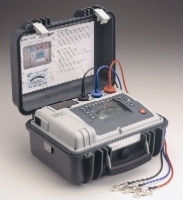
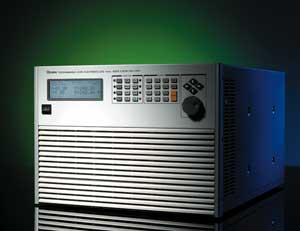
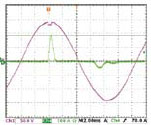
Figure 7: Transfer time for Off-Line UPS

Automatic Bandwidth Adjustment (ABA)

When the UUT, such as one shown in Figure 8, has a higher output impedance, the current waveform will not be stable without ABA. In most cases, the loading current will be oscillating and spoil the test.

Note 1: A test current will be programmed prior the actual loading defined by user for impedance detection.

Parallel / 3-Phase Control

The 63800 series provides parallel and 3-phase functions for high power and three phase applications. All the models within the 63800 series can be used together for both parallel and 3-phase functions as well as paralleled AC Load units in a 3-phase configuration, providing excellent flexibility and cost savings for the 63800 series AC load.

Figure 10: Parallel connection


Figure 11: Parallel/3-Phase Y connection


Figure 12: Parallel/3-Phase Delta connection

Auto Power Factor Correction

Setting the power factor is one of the major features to the 63800. The power factor is defined as:

Since PF is a function of real time voltage and current, traditional AC load designs assume the voltage waveform to be sinusoidal all the time, as seen Figure 13. This is not realistic because the voltage waveform may be distorted after the load is applied shown in Figure 14.

Figure 13

Figure 14

Programmable High Power

63802 Programmable AC Electronic Load 1800W/18A/350V

63803 Programmable AC Electronic Load 3600W/36A/350V

63804 Programmable AC Electronic Load 4500W/45A/350V

Request a quote

Insulation Testing for Railroads

April 20th, 2011

Railroad Insulation Testing Applications

Railroads rely heavily on cable maintenance to keep the trains running. Signal cables, as well as other types in critical functions, are subjected to considerably more stress than are cables in more tranquil environments. Heavy-duty rail yards, highway crossings, public access areas, industrial feeder lines, and so on, make up a patchwork of varied environments that contribute heavily to wear and tear. Accordingly, railroads have commonly learned the value of the preventive maintenance concept. With schedules to be met and traffic crossings to be kept clear and safe, reactive maintenance after a breakdown is virtually out of the question in critical functions. Cables are tested on a regular maintenance schedule that includes insulation testing.

Commonly employed acceptance values for signal cables are 200,000 and 500,000 Ohms. If the cable tests above 500,000 W (0.5 MW), it is passed. If between 500,000 and 200,000 W (0.2 MW), it is earmarked for a more dedicated test schedule (typically, every 12 months). If below 200,000 W, it is pulled and replaced immediately.

Obviously, Megger Insulation Testers are the instrument of choice for this application. The wide variety of models that will meet this fairly general requirement enable the prospective customer to satisfy both budget restraints and personal preferences on a number of additional functions. The cables involved are generally 600 V, so that the operator can readily choose between a 500 V “operational” type of test or a 1000 V “stress” test. Since most models offer both of these test voltages, this is an easy match. The pass / fail range is also readily met, but just be careful to keep the customer apprised of the units of measurement in which they will be working: one half, and two tenths, of a MegOhm. On Major Meggers, the analog scale shows divisions at the required values: 0.5 is marked as such, and 0.2, while not specifically noted, is the next “tick” mark above 0.1. These are both readily distinguishable in terms of pointer travel. The digital model (210600) will display the desired values as 0.20 and 0.50. Hand-held models also provide the correct divisions, essentially the same as do the Majors, whether digital or analog. And while 5 kV models may represent overkill in terms of test voltage, the MJ15 & BM15 models do offer the plastic overlay accessory that can be conveniently marked with the desired pass/fail values to help reduce the possibility of operator error in interpreting and recording results. It should be noted, however, that with these models, the amount of pointer travel in the desired range is reduced compared to that of Majors, because of their overall greater measuring range.

And remember, the general testing concepts adopted by the railroads apply just as well to all cable applications, with modifications to the particular industry. If you have railroads among your customer base, talk to the cable maintenance foreman or supervisor, and indicate the value of a Megger Insulation Tester in keeping the railroads chugging. (Jeff Jowett; Senior Applications Engineer)

Click on Image for a Larger View

500 Megahertz of Spectrum over the Next Ten Years

April 5th, 2011

The Plan – 500 Megahertz of Spectrum over the Next Ten Years for Expanded Wireless Broadband

NTIA, with input from the Policy and Plans Steering Group (PPSG), produced a Ten-Year Plan and Timetable (hereafter referred to as the Plan) to meet the President’s 500 megahertz goal. The Plan, dated October 2010, identified steps to determine candidate bands, to assess their feasibility, and to identify the actions necessary to make spectrum available for broadband wireless services. The Plan also described the processes and timetable for executive branch actions in support of the Administration’s goal. Fully implemented, the Plan requires consideration of a number of factors, including technical and operational considerations of Federal systems and non-Federal broadband wireless systems, the costs to evaluate and implement sharing methods or relocate Federal systems, and the identification of comparable spectrum for relocating an incumbent system. The Plan also takes into account the Presidential Memorandum’s statement that “the plan and timetable must take into account the need to ensure no loss of critical existing and planned Federal, State, local, and tribal government capabilities, the international implications, and the need for enforcement mechanisms and authorities.”

NTIA selected and ranked six blocks of spectrum for priority consideration for re-purposing to non-Federal use for FCC-licensed wireless broadband systems:

1. 1755 – 1850 MHz
2. 1695 – 1710 MHz
3. 406.1 – 420 MHz
4. 1370 – 1390 MHz
5. 4200 – 4400 MHz
6. 3500 – 3650 MHz

On January 28, 2011, NTIA selected 1755-1850 MHz as the first block for detailed evaluation of the possibility of repurposing for wireless broadband. NTIA chose this spectrum for several reasons, including the nature of current Federal agency use of the spectrum, the likelihood of successfully repurposing within ten years, the international harmonization with mobile operations, the existence of mature wireless equipment, and the spectrum’s advantageous propagation characteristics for mobile operations. To assist the Federal agencies in conducting their evaluation, NTIA developed a set of spectrum for potential comparable spectrum for relocation from 1755-1850 MHz, and provided the set to the Federal agencies for review and analysis. NTIA continues to conduct technical analyses on 1755-1850 MHz and comparable spectrum bands and plans to complete the detailed evaluation of this band by September 30, 2011.

On January 19, 2011, in furtherance of the Fast Track recommendations, NTIA formally recommended to the FCC that it take regulatory action to repurpose the 1695-1710 MHz and 3550-3650 MHz bands for wireless broadband use on a shared basis.8 On March 8, 2011, the FCC released a Public Notice seeking comment on the steps the Commission could best promote wireless broadband deployment for these bands. NTIA is also pursuing repurposing the 4200-4400 MHz band and 1695-1710 MHz band as part of a proposal for a broad agenda item on broadband wireless access for the WRC-2016. In conjunction, the Federal Aviation Administration (FAA) is conducting a technical analysis of the 4200-4400 MHz band with assistance from the affected Federal agencies.

NTIA, together with the Federal agencies and the PPSG, is working to implement the Plan in accordance with the Plan timelines. Pursuant to the Fast Track Evaluation, NTIA has recommended to the FCC that it act to make 1695-1710 MHz and 3550-3650 MHz bands available for wireless broadband use on a shared basis. In addition, the FAA has begun technical analyses of the entire 4200-4400 MHz band with technical assistance and input from other the affected Federal agencies and NTIA will continue to pursue a proposal for a broad agenda item at WRC-2016 on broadband wireless access to include the 4200-4400 MHz band and the 1695-1710 MHz band. For the overall Plan, FCC is working closely with and updating PPSG members on regulatory actions and the FCC may seek public input as appropriate on non-Federal system requirements/characteristics and public comment on those candidate bands sufficiently early in the process to allow time to complete allocation and service rulemaking proceedings. Follow-on necessary FCC actions may include modifying the Allocation Table, service rule-makings, promulgating incumbent relocation policy and requirements and auction rules where appropriate. The Office of Management and Budget has inserted proposals in the FY 2012 Budget to provide more flexibility to the Spectrum Relocation Fund to create a more efficient relocation process. NTIA has developed a work plan and guidelines for the Federal agencies via the PPSG and PPSG-SWG for the 1755-1850 MHz band study to aid completion of the detailed evaluation for the 1755-1850 MHz by September 30, 2011. Each of the above actions will contribute to making 500 MHz of spectrum available for mobile and fixed wireless broadband in ten years. (source www.ntia.doc.gov)

Download the Full NTIA Progress Report in PDF Format Here

What is the NTIA ?

The National Telecommunications and Information Administration is an agency in the U.S. Department of Commerce that serves as the executive branch agency principally responsible for advising the President on telecommunications and information policies. In this role, NTIA frequently works with other Executive Branch agencies to develop and present the Administration’s position on these issues. Since its creation in 1978, NTIA has been at the cutting edge of critical issues. In addition to representing the Executive Branch in both domestic and international telecommunications and information policy activities, NTIA also manages the Federal use of spectrum; performs cutting-edge telecommunications research and engineering, including resolving technical telecommunications issues for the Federal government and private sector; and administers infrastructure and public telecommunications facilities grants.