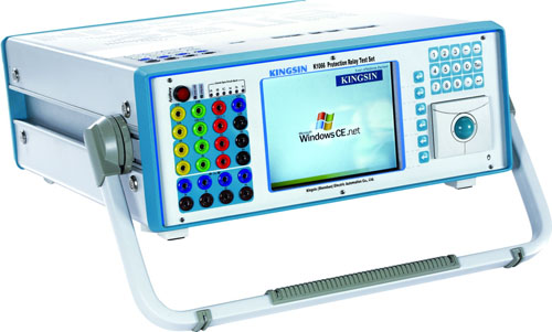
The Properties of Grounding Distance using the Kingsine Relay Test Set |
||||||||||||||||||||||||||||||||||||||
| Kingsine K10\K20\K30 Series
Device: GE L90 Line Differential Relay
Fixed Value Menu:
Grounding Distance Graph (GE Software) Testing Connection: A. Connect the output terminals of three-phase voltage and current IA of the relay test set with the corresponding input terminals of the protection device by test wire. B. The triggering contact of the protection device is connected with Binary Input terminal A of the relay test set. C.Open Advanced Distance I module,setting test parameter
Basic Parameter
Time and Fault Type After the setup is finished, click ‘Run’ button on the right upper corner and begin the test
Result Graph Kingsine K1063i Protection Relay Test Set |
The following two tabs change content below.


Mike is a finance industry executive with expertise in test, IT and avionics equipment acquisition, resale, residual valuation, leasing, renting and consignment.
Latest posts by Mike Novello (see all)
- Used Bio-Rad Gel Doc XR For Sale - March 9, 2022
- CONSULTIX WTX-35-A4 CW Test Kit For Sale - November 9, 2021
- Biologic SP-150 Single Channel Potentiostat and VMP3B-80 Booster For Sale - September 7, 2021


