
Agilent 8753 Series Network Analyzer Basics
![HP_8753ES-006[1]](http://blog.testequipmentconnection.com/wp-content/uploads/2013/05/HP_8753ES-0061.jpg)
This is a basic system operational check procedure for the 8753 series of Network Analyzers. These analyzers have changed through the years. But the key strokes have stayed basically the same as this product has evolved. The main differences are the unit went from a four port system with an RF out, an R port, an A port and a B port with an optional external S-parameter test set, to an integrated S-parameter set. Agilent also went to a 7mm genderless connector from the type N connector used on the four port machines. The four port machines were available in both 50 ohm and a 75 ohm option. The two port units were also available in a 50 ohm model and optional 75 ohm ports. The 50 ohm versions had the 7mm connectors and the 75 ohm units were built with 75 ohm type N connectors. The units which are 75 ohm are clearly marked on the front of the units either above or below the connectors.
The following items will be needed for the system tests 21 and 22, which can be completed using this procedure.
For the two port systems the following items will be needed:
- A known good dependable short.
- Appropriate adapters needed to connect the short to the port.
For the four port systems the following items will be needed:
- An in line 20dBm attenuator. (Note: Do not attempt to use a mechanical or electronic attenuator with cables. This will not give a passing result. )
- A power splitter (HP/ Agilent 11667A or equivalent)
- Any appropriate adapters needed to make the connections
- Two known good dependable cables.
Note - Be sure to always consider the connector type and impedance of the connectors to avoid damage.
The steps below outline the keystrokes and actions needed to complete a full basic automated self-test system located in the unit’s software.
- Plug in and apply power to the unit.
- Power on the unit and allow it to warm up for at least 30 minutes.
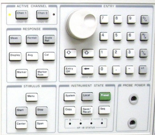
- Locate and press the “SYSTEM” button on the front panel.
- Locate and press the [SERVICE MENU] soft key.
- Locate and press the [TESTS] soft key. The unit will display a message TEST 1 PRESET PASS if the unit did pass the initial power on tests. If it did not pass the unit will display FAIL in place of pass.
- Locate and press the soft key [EXECUTE TEST] the unit will then rerun the power on self tests. The unit performs this test at every power on or preset. The unit will again display the message TEST 1 PRESET PASS
- Locate and press the “UP ARROW” button on the front panel.
- Confirm the unit should displays TEST 2 ROM PASS.
- Locate and press the “UP ARROW” button on the front panel. Continue to press the “UP ARROW” button to confirm that the unit has passed the test numbers 3 through test 11.
- Locate and press the “UP ARROW” button again on the front panel. The unit will go to test 12 and display TEST 12 FR PAN WR/RD -ND-
- Locate and press the [EXECUTE TEST] unit will run the test and display a message TEST 12 FR PAN WR/RD PASS.
- Locate and press the “UP ARROW” button on the front panel. The unit will display the message for the test.
- Press the soft key [EXECUTE TEST]. Unit will run test 13, upon completion the unit will give a PASS message in the standard format as previously described.
- Press the “UP ARROW” key to view and confirm all tests have passed from test 14 through test 16.
- Continue to use the “UP ARROW” button and [EXECUTE TEST] soft key as previously described for tests 17 through test 20.
- Press the “PRESET” button
- Press the “SYSTEM” button
- Press the [TESTS] soft key
- With the numeric key pad enter the following key strokes.
- Press the “2” button
- Press the “1” button
- Press the “1x” button
- Unit will display TEST 21
- Press the [EXECUTE TEST] soft key. The unit will display instructions for connections that need to be made to perform the test. If the unit is a two port system the unit will require a short with appropriate adapter connecting it to the unit. If the unit is a four port analyzer the unit will need a 20dBm attenuator connected to the unit then a power splitter then a cable to port A and another to port R.
- Press the [CONTINUE] soft key. The unit will then run the test 21. After completion the unit will display PASS.
- Note: IF a FAIL condition experienced. This could be cause by dirty connectors, dirty or faulty adapters, or over tightening of the connections.
- Press the “UP ARROW” button.
- Unit will display TEST 22.
- Follow steps 17 and 18 with respect to port two on the two port units and port B to R port.
- Unit should display a PASS condition. IF this test fails take consideration to the not in step 18.
The Network Analyzer has now preformed the basic tests to ensure the system is functioning properly. Although this does test most all of the unit, other failures may be encountered during a full calibration procedure. This operational test procedure does not correct calibration or change anything in the unit but only tests the vital functions in a short time period.
Learn more about Network Analyzers
Should you need a network analyzer we have many to choose from depending on your frequency rage and budgetary needs.
Latest posts by Mike Novello (see all)
- Used Bio-Rad Gel Doc XR For Sale - March 9, 2022
- CONSULTIX WTX-35-A4 CW Test Kit For Sale - November 9, 2021
- Biologic SP-150 Single Channel Potentiostat and VMP3B-80 Booster For Sale - September 7, 2021