Save Thousands with Vibration Analysis Package

November 11th, 2010

Save Thousands with the Commtest Vibration Analysis Package Promotion – Limited Time Only


LeCroy LogicStudio Demo Video

November 11th, 2010

LeCroy Demo at the 2010 Embedded Systems Conference

LeCroy LogicStudio Logic Analyzers – Logic analyzers are known to be slow, complicated and expensive but Logic Studio changes all this by delivering a powerful feature set, high performance hardware and an intuitive point and click user-interface. With timing cursors, history mode, I2C, SPI and UART decoding, powerful triggering and simple navigation the PC is transformed in to an all-in-one debug machine. Pair the LogicStudio 16 with a WaveJet 300A oscilloscope and debug systems with analog, digital and serial data signals.

Unique Feature Set

From basic tools like timing cursors that snap to the edge of a waveform to protocol decoding of I2C, SPI and UART busses LogicStudio provides a rich feature set for faster, smarter debug. History mode will display previously captured data and the powerful, flexible triggering will help solve the most complicated problems.

Easy to Use

The intuitive user-interface works with basic mouse operations. To pan the waveforms simply click and drag, Use the mouse wheel to zoom in or scan the waveforms with the magnification toll to get a great view of the details. With all the debug tools accessible from the main screen, debugging is simple, efficient and just 1 mouse click away.

Digital, Serial, Analog

Turn the PC into a mixed signal oscilloscope by connecting both a LogicStudio 16 and a WaveJet 300A oscilloscope. View digital, serial and analog waveforms simultaneously, directly on the PC display. This combination of waveforms provides insight that a traditional logic analyzer cannot. 

Request Your Quote HERE

RF Calibration Cost Cutter

November 5th, 2010

Cut
the cost of RF calibration in half

The Fluke 9640A Series is the key component in an RF and microwave calibration system. It enables you to accurately calibrate a broad RF measurement workload at half the cost of a typical high performance calibration system.

Unlike general purpose signal generators, the 9640A Series dramatically improves efficiency and capacity by reducing complexity, de-skilling, and speeding up calibration times. Automating calibration using MET/CAL Plus software to take control of the unit or device under test and all system instruments will increase system capacity by up to 25% and free 50% of the system operator’s time to perform other tasks.

What’s New?

  • 9640A-LPNX model with reduced close-in phase noise and
    specifications down to 1 Hz offsets
  • Enhanced leveled sine level and attenuation accuracy
  • Optional integrated 50 MHz frequency counter
  • Unique 10 uHz enhanced leveled sine frequency setting
    resolution at all frequencies
  • Leveled sine minimum output frequency of 1 mHz
  • External phase modulation
  • Narrow range-locked sweep
  • New accessory: 9600FLT 1 GHz wide offset phase noise filter

Find out how the Fluke 9640A Series can be the key component in your RF and microwave calibration system:

Get product details and request a quote

DTV Network Monitoring Solutions

November 3rd, 2010

Triveni Digital Streamscope Targeted for DTV Network Monitoring

Ensuring the Integrity of DTV Streams
The 4th generation StreamScope product line targeted for DTV networks enables efficient stream quality monitoring, analysis and troubleshooting on an enterprise-wide scale. Indispensable in the station or any network location, rack-mountable and portable models are available with ASI, VSB, SMPTE 310, QAM, 8VSB, QPSK and Gigabit Ethernet input support. The new StreamScope products work together to enable cost-effective deployment across a broadcast operation, whether on a local, regional, or national scale, and the systems have open interfaces to enable easy integration with third party products. The use of standard formats for capturing of recorded streams helps achieve this high-level of third party integration support. Innovative elements of the new StreamScope architecture include a rule-based monitoring system and associated rule creation tools, the Business Intent Assurance feature and stream transformation monitoring.

The StreamScope RM-40 is a low cost stream monitoring appliance. The real-time RM-40 remotely monitors, measures, records, and analyzes DTV streams to ensure their integrity, reliability, and compliance with standards. The RM-40 can be monitored from any SNMP agent in the network and alarms can be distributed via email, SMS, or SNMP traps. In addition, interfaces to GuideBuilder metadata management systems and the Business Intent Assurance feature validate that the streams are well formed from a standards perspective, and automatically ensure that the streams comply with the business model of the operation. Other RM-40 innovations include stream profiling and comparison and template learning. The small form factor unit is virtually maintenance free and may be placed anywhere in the broadcast network including repeater stations where there may be no on-site staff.

The StreamScope MT-40 provides end-to-end, MPEG-2/MPEG-4 transport stream monitoring and analysis for DTV signals carried by broadcast, cable, satellite, IPTV, or mobile networks. Key features include QPSK, 64/256 QAM, ASI and GigE, plus file inputs, remote monitoring capabilities, and IP routes analysis.

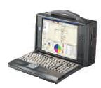
Check out the awesome new Triveni Digital STSC-MT-40-LCP-B. StreamScope MT-40LCP Low Cost Portable with battery

The StreamScope MT-40 provides end-to-end, MPEG-2/MPEG-4 transport stream monitoring and analysis for DTV signals carried by broadcast, cable, satellite, IPTV, or mobile networks. Key features include QPSK, 64/256 QAM, ASI and GigE, plus file inputs, remote monitoring capabilities, and IP routes analysis. Maximum of 2 inputs.  More Info HERE

Special MT-40 Bundle Promotion for Non-USA Users HERE
This cost saving package includes:

  • STSC-MT-40-LCP-B – StreamScope MT-40LCP Low Cost Portable with battery
  • STSC-OPT-ASI – ASI Single Input Module
  • STSC-OPT-AOUT – ASI Playout Software 38.8 Mbps, File Loop
  • STSC-OPT-GLCP – Non Real Time Analysis – without PCR Analysis. Licensed option, available for StreamScope Low Cost LCP

Who is Triveni Digital?

Triveni is a Sanskrit word meaning convergence. It represents their commitment to the convergence of data with digital broadcasting. It also symbolizes the Triveni Digital suite of products, each independently powerful, yet synergistic with one another. Coming from a heritage of innovation, Triveni Digital (formerly the LG Electronics Research Center of America) continues to be backed by LG Electronics-a major player in the consumer electronics industry. Their strong set of partners, and standards-based open systems approach has enabled them to provide flexible, scalable and robust best-of-breed solutions to customers.

Optimizing Management of Digital Broadcasts
Triveni Digitals innovative products are already helping to operate DTV facilities across the country, Triveni engineers and designers are the professionals setting the standards for the whole DTV industry.

Getting Your Signal Where it Needs to Go
The Triveni product suite is designed to make sure that your DTV signals are carried and received correctly. From GuideBuilder’s market-share-leading PSIP technology to StreamBridge’s accurate data translation to StreamScope’s powerful analytical capabilities, we deliver-flawlessly.

Creating Sustainable Value for Digital Broadcast
Unique, field-tested products and services let you start taking advantage of new revenue opportunities and new business models. Data broadcasting, digital billboards, homeland security, interactive TV, etc.

New AEMC Ground Resistance Tester

October 28th, 2010

AEMC introduces the New Ground Resistance Tester Model 6471

The Ground Resistance Tester Model 6471 is a portable measurement instrument designed to measure Ground Resistance using 2 current clamps (no auxiliary rods). Other test methods provided are: Ground Resistance (3-Pole or 4-Pole), Ground Coupling, Bond Resistance, Selective Ground Resistance and Soil Resistivity (Wenner or Schlumberger method). The Model 6471 measures from 0.01 to 99.99kΩ and is auto-ranging, automatically seeking out the optimum measurement range and test current. Easy-to-use – Simply connect the leads, select the test mode, press Start and read the results.  Up to 512 test results can be stored in internal memory for later recall to the display or download to a PC via DataView software. The Model 6471 is Cat. IV rated to 50V and is over voltage protected to more than 250VAC against accidental connection to live circuits. The voltage is also displayed on screen. Additional features of the 6471 include a heavy-duty field case sealed against dust and water when closed (the test button is also sealed against the elements); manual and automatic test frequency selection from 41 to 513Hz; user selectable 3-Pole Fall-of-Potential or 4-Pole Soil Resistivity test methods and user selectable 2-Pole or 4-Pole Bond Resistance test method. The Model 6471 is rugged, easy-to-use and ideal for maintenance crews performing numerous tests. It exceeds mechanical and safety specifications for shock, vibration and drop tests per IEC standards. The adjustable test frequency provides for rejection of high levels of interference, allowing it to be used under difficult conditions such as high stray currents that normally affect accuracy.

Applications:

  • 3-Point measurements of resistance to ground on ground rods and grids
  • 4-Point tests of soil resistivity measurements
  • Touch and Step potential testing measurements
  • 2- or 4-Wire tests for continuity tests on bonding or on grounding systems
  • Earth Coupling measurement and display

The AEMC Model 6471 is Available in Complete Kit Form:

AEMC 6471 Kit – 300 ft Multi-Function Ground Resistance Tester – includes meter, set of two SR182 current probes, rechargeable NiMH batteries, optical USB cable, power adapter 110/240V with power cord 115V US, two 300 ft color-coded leads on spools (red/blue), two 100 ft color-coded leads (hand-tied, green/black), four T-shaped auxiliary ground electrodes, set of five spaded lugs, one 100 ft AEMC tape measure, DataView software, ground tester workbook CD, carrying bag for meter and carrying bag for kit.  View and Purchase this convenient Kit HERE

AEMC Instruments manufactures professional electrical test and measurement instruments for the industrial, commercial and utility marketplace. Founded in 1893, their products are backed by over 100 years of experience in test and measurement equipment, and encompass the latest international standards for quality and safety. AEMC is the industry leader in current measurement probes, ground resistance testers and insulation resistance testers. Their full product line also includes clamp-on meters, ratiometers, power meters, harmonic power meters, data loggers, lightmeters and numerous other electrical test tools.

Electric Vehicle Testing Solutions

October 20th, 2010

Automatic Test System – Chroma 8000

The power conversion section of the EV / HEV is composed of several power electronic units, which include the EVSE (EV Supply Equipment), on-board charger, DC/DC converter, motor driver, etc. The Chroma ATS (Automatic Test System) addresses the specialized requirements involved in testing the power electronics during not only the development phase, but also the production phase. The benefits of our ATS are not limited to the reduction of manpower and prevention of human error; they also include advanced features such as automatic test data recording and creation of statistical analytical reports for later design review or product improvement. There are custom-built systems that are designed specifically for certain power electronic units; however, these systems are usually difficult to maintain and lack flexibility. These shortcomings will definitely impede the product development process as test methodologies evolve.

EV TestThe Chroma 8000 ATS is a standard test platform that solves the conventional problem of self designed ATS’s for power electronics testing. It is built on testing technology and experience in the power electronics industry, where Chroma has been a technological leader for over 20 years. Chroma has provided over 1,500 Chroma 8000 ATSs to customers worldwide that are being used in R&D, QA departments and production lines. Our test system is designed to have an open architecture, allowing the user to easily integrate various instruments. The Chroma 8000 ATS includes a wide range of hardware choices such as AC/DC power supplies, Electronic Loads, Power analyzers, Oscilloscopes, Digital multi-meters, as well as various digital/analog I/O cards. This flexibility combined with an open architecture gives the user an adaptable, powerful and cost effective test system for the EV / HEV power electronics. The Chroma 8000 test system includes a sophisticated test executive, which includes pre-written test items. Users may also create new test items by using the Test Item Editor function. This provides the flexibility to expand your test library without limits. The Chroma 8000 ATS’s ability to satisfying the test requirements for multiple power electronic units is key to keeping consistency and reducing costs during the transition between R&D and production.

The following pictures of the Chroma ATS show some applications for EV / HEV. The system will not only perform the tests and report it to an isolated PC, but it will also network to the shop-floor (MES) system for production line for data log-in, analysis and monitoring.

ATS Applications

Software Platform of ATS Chroma 8000

PowerPro III provides users with an open software architecture suited to a wide range of applications and devices. The test item editor is a powerful tool which is similar to C language, but much easier to use. It allows users to define test procedures, test condition variables, test result variables and temporary variables. The test program editor also provides a useful means to link several pre-defined test items for batch testing.

Customized ATS for EV/PHEV Maintenance Application

EV Auto ServiceCharger Station

The demand for charging stations is steadily growing as EV / PHEV’s gain popularity. Unlike the conventional gas station, which mainly consists of mechanical parts, the EV / PHEV charging station has Implemented sophisticated electronics for metering, controlling, and measuring the amount of energy required and transferred to the vehicle. In order to keep the charging station in optimum operating condition and maintain its accuracy, frequent service and calibration is required. Chroma has the capability to provide a customized mobile service system, which is specifically designed to perform diagnosis, measurement and meter calibration for these charging stations.

Auto Service

With the power train system switching from internal combustion engine (ICE) mechanical design to fully electric power train design, ICE oriented auto mechanics must quickly familiarize themselves with the electrified system. In order to provide optimum vehicle operating conditions, maintain serviceability and minimize the chance of a mechanics exposure to electric shock hazards, the Chroma 8000 provides unique, dynamic diagnostic capabilities. These include: vehicle battery unit testing, voltage/current parameter measurement reading, CAN bus interface, diagnostic reporting, etc. The test system provides diagnostic data through the internet directly to the vehicle manufacturer for data analysis.

EV Flowchart

View
and Purchase Chroma Solutions HERE

Meriam M4 Series Calibrators Available Now

October 14th, 2010

Meriam M4 Series Calibrators Now Available from Test Equipment Connection

Field Calibration & Data Logging Just Got Easier!  With Meriams M4 Series Pressure & mA Calibrator M400 Best in class accuracy, compact, easy to use and easy to read!

Precisely measure, sink or source DC voltage or current. Selectable (accuracy or precision) display resolution.  Precision feature increases resolution to the right of decimal place. NEW Adaptive Interface Wheel to navigate scroll lists and dial in precise values. Wide selection of pressure ranges for the M401 (Single Pressure Sensor) or M402 (Dual Pressure Sensors). Click Here to Learn More

Log data to dedicated 4GB SD card and retrieve via USB port!

Specifications & Features:

Pressure +0.025% of Reading from 10 to 100% of range and +0.002% of Full Scale below 10% of Range

Electrical (+0.015% of Reading and +0.002 units)
Fully temperature compensated from -20° C to +50° C

Log data for up to 3 channels (1 [M400] or 2 [M402]) pressure, voltage or current – up to 100 individual log files

Free PC application for creating standard .csv files

30+ hours battery life

Megger Best Practices Battery Maintenance and Substation Seminars

October 12th, 2010

Free Megger Best Practices Battery Maintenance and Substation Seminars

Megger Best Practices Battery Maintenance and Substation Seminars now in Atlanta, Georgia and Orlando, Florida

Secondary batteries play an essential role in many areas of business and commerce, but to be sure that they deliver their full performance when called upon to do so, regular testing is needed.

To learn more Megger is presenting FREE one-day seminars across the United States and recently we have added events in Georgia and Florida. The seminars address some of the most important and costly issues relating to battery and substation maintenance, and include extensive practical
presentations.

Megger’s Best Practices Battery and Substation Seminars are being held at the following locations:

October 26th
Holiday Inn Atlanta/Roswell
909 Holcomb Bridge Rd.
Roswell, Georgia 30076
click here to register

October 28th 2010
Holiday Inn Main Gate
5711 West U.S. Hwy 192
Kissimmee, FL 34746
click here to register

Focus
The key focus of the Best Practices Battery and Substation Seminar is condition analysis, and the assessment of power transformers. All sessions include show-and-tell demonstrations of practical techniques for maximizing reliability, including the most commonly used methods and practices.

Among the topics covered in detail for circuit breakers are basic testing techniques, first trip testing, static and dynamic resistance measurements, vibration analysis, the formulation of test plans and reporting.

For power transformers, recent advances in condition analysis and assessment are presented, complemented by discussion and demonstration of the most useful and convenient test techniques. These include power factor testing, sweep frequency response analysis (SFRA) and insulation diagnostic analyzer (IDAX) applications.

Invaluable information is also provided on Battery Performance Testing and Reporting data collection, trending and analysis via PowerDB software, as well as insights into how companies are coping with the North American Electric Reliability Corporation (NERC) and Federal Energy Regulatory Commission (FERC) data collection and management requirements.

Participants of this training seminar will improve business skills, share insights, and learn from Megger’s technology specialists as they share their expertise by addressing many of the challenges seen in the electric power industry today. Topics will highlight HV Circuit Breaker Testing and Condition Analysis, and Assessment of Power Transformers. Each session will include show and tell demonstrations on the practical aspects of ensuring reliability including common methods and practices.

Sign up early as spaces are limited. Please contact Nicole Stokes at 214 330 3245 or email nicole.stokes@megger.com to register.

(source  www.megger.com)

View and Purchase Megger Products HERE


NIST Identifies Smart Grid Standards

October 11th, 2010

NIST Identifies Five Foundational Smart Grid Standards

The Commerce Department’s National Institute of Standards and  Technology (NIST) has advised the Federal Energy Regulatory Commission  (FERC) that it has identified five “foundational” sets of standards for Smart  Grid interoperability and cyber security that are ready for consideration  by federal and state energy regulators.

The standards, produced by the International Electrotechnical Commission (IEC), focus on the information models and protocols important to efficient and reliable grid operations as well as cyber security.


In a letter to FERC Chairman Jon Wellinghoff, NIST’s national coordinator for Smart Grid interoperability, George Arnold, said the standards “are essential to uniform and interoperable communication systems throughout the grid and will accommodate the evolution of the grid and the integration of new technologies.”

In the Energy Independence and Security Act (EISA) of 2007, Congress directed NIST to coordinate development of communication protocols and other standards to achieve an interoperable Smart Grid —a nationwide electric power system that enables two-way flows of energy and information.  Under EISA, once it determines sufficient consensus has been achieved, FERC is charged with instituting rulemaking proceedings to adopt the standards necessary to ensure Smart Grid functionality and interoperability.

The five families of IEC standards will further efforts to achieve efficient and secure intersystem communications, among other FERC priorities identified in the commission’s July 16, 2009, Smart Grid Policy Statement.  These standards will be updated as Smart Grid requirements and technologies evolve.

The standards and their functions are:

  • IEC 61970 and IEC 61968: Providing a Common Information Model (CIM) necessary for exchanges of data between devices and networks, primarily in the transmission (IEC 61970) and distribution (IEC 61968) domains.
  • IEC 61850: Facilitating substation automation and communication as well as interoperability through a common data format.
  • IEC 60870-6: Facilitating exchanges of information between control centers.
  • IEC 62351:  Addressing the cyber security of the communication protocols defined by the preceding IEC standards.

To determine whether a standard was ready for consideration by regulators, NIST took a number of factors into account, including the maturity of the standard, the resolution of previously identified issues by its Smart Grid Interoperability Panel, and a satisfactory review of cyber security requirements.

The five IEC standards were among the 25 Smart Grid-relevant standards identified as “ready for implementation” in the NIST Framework and Roadmap for Smart Grid Interoperability Standards, Release 1.0, which was issued in January 2010.  However, these specifications required a cyber security review that could not be completed until NIST finalized its initial Guidelines for Smart Grid Cyber Security, which were published in early September 2010.

NIST anticipates that the release of future standards identified as ready for consideration by regulators—as well as by other Smart Grid stakeholders—also will be organized according to Smart Grid functions and domains of application, such as bulk generation, transmission or customer premises.

NIST’s standards-coordination activities are supported, in part, by the U.S. Department of Energy, the lead agency for federal Smart Grid efforts.

To read summaries of each of the five standards identified for consideration by regulators, go to: http://collaborate.nist.gov/twiki-sggrid/bin/view/SmartGrid/NISTStandardsSummaries (source www.nist.gov)

Webb Telescope Snapshot: Cryo-Testing

October 8th, 2010

The James Webb Space Telescope

The ISIM structure is inspected inside NASA’s Space Environment Simulator at the Goddard Space Flight Center after enduring weeks of temperatures less than minus 300 degrees Fahrenheit; the same temperature it will see for the duration of its mission inside the James Webb Space Telescope.

The James Webb Space Telescope (JWST) is a large, infrared-optimized space telescope, scheduled for launch in 2014. JWST will find the first galaxies that formed in the early Universe, connecting the Big Bang to our own Milky Way Galaxy. JWST will peer through dusty clouds to see stars forming planetary systems,connecting the Milky Way to our own Solar System. JWST’s instruments will be designed to work primarily in the infrared range of the electromagnetic spectrum, with some capability in the visible range. JWST will have a large mirror, 6.5 meters (21.3 feet) in diameter and a sunshield the size of a tennis court. Both the mirror and sunshade won’t fit onto the rocket fully open, so both will fold up and open once JWST is in outer space. JWST will reside in an orbit about 1.5 million km (1 million miles) from the Earth. The James Webb Space Telescope was named after a former NASA Administrator.

Watch the Webb In Progress on the NASA “Webb-cam”! http://www.jwst.nasa.gov/webcam.html

Currently on The Webcam Page

The Near-InfraRed Camera Engineering Test Unit (NIRCam ETU), the Near-InfRared Spectrograph Engineering Test Unit (NIRSpec ETU), and the Mid-InfraRed Instrument Structural Thermal Model (MIRI STM) are currently in the cleanroom. They are visible near the left side of the below image. The NIRCam ETU will go through electrical interface checks as well as mechanical fit checks. The NIR Spec ETU will undergo a series of electrical tests to confirm its operation as well as mechanical interface checks with the Integrated Science Instrument Module (ISIM) Structure. The MIRI STM serves as the engineering test unit for MIRI and will be integrated into the ISIM Structure.

(Left Side of the Clean-Room)

The ISIM Structure, the large, black, square, “latticed” structure was temporarily moved out of the cleanroom and into Cryo Set Testing, but now it is back, as you can see on the webcam. The testing it underwent was designed to observe the ISIM structure with high precision photogrammetry equipment as it is cooled from room temperature (20 C or 68 F) to -233 C (-388F) and ensure the amount the structure shrinks is within the allowable and predicted bounds. The test cycles between these two temperatures five times to show that the structure behaves in a repeatable fashion over these cycles. The ISIM Structure will contain all of the Webb’s instruments and will sit right behind the primary mirror. Also in the cleanroom right now is the OSIM (Optical Test Element Simulator), visible in the lower right (along with part of the balcony the camera is on) below. This equipment provides a high fidelity representation of the Webb telescope section and is used for performing detail optical testing of the ISIM and its instruments.

(Right side of the Clean-Room)